Graphic Audio Equalizer Example
- group Graphic Audio Equalizer Example
Refer riscv_graphic_equalizer_example_q31.c
- Description:
This example demonstrates how a 5-band graphic equalizer can be constructed using the Biquad cascade functions. A graphic equalizer is used in audio applications to vary the tonal quality of the audio.
- Block Diagram:
The design is based on a cascade of 5 filter sections.
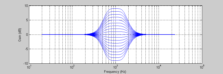
Each filter section is 4th order and consists of a cascade of two Biquads. Each filter has a nominal gain of 0 dB (1.0 in linear units) and boosts or cuts signals within a specific frequency range. The edge frequencies between the 5 bands are 100, 500, 2000, and 6000 Hz. Each band has an adjustable boost or cut in the range of +/- 9 dB. For example, the band that extends from 500 to 2000 Hz has the response shown below:


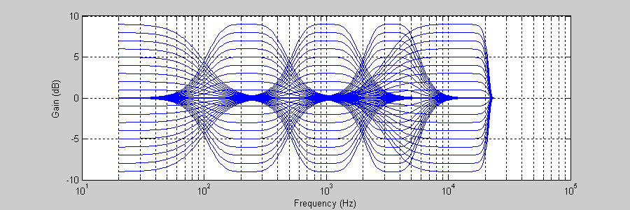
With 1 dB steps, each filter has a total of 19 different settings. The filter coefficients for all possible 19 settings were precomputed in MATLAB and stored in a table. With 5 different tables, there are a total of 5 x 19 = 95 different 4th order filters. All 95 responses are shown below:

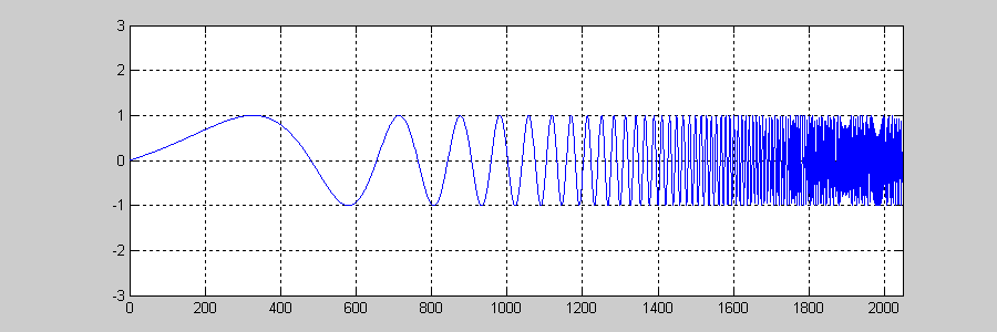
Each 4th order filter has 10 coefficents for a grand total of 950 different filter coefficients that must be tabulated. The input and output data is in Q31 format. For better noise performance, the two low frequency bands are implemented using the high precision 32x64-bit Biquad filters. The remaining 3 high frequency bands use standard 32x32-bit Biquad filters. The input signal used in the example is a logarithmic chirp.

The array
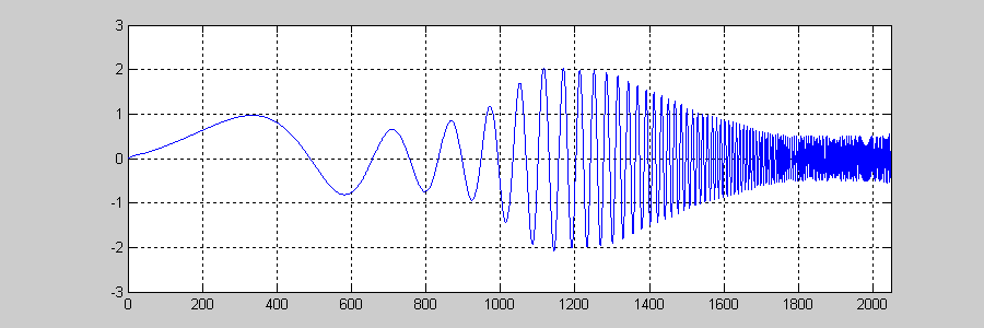
bandGainsspecifies the gain in dB to apply in each band. For example, ifbandGains={0, -3, 6, 4, -6};then the output signal will be:
- Variables Description:
testInput_f32points to the input datatestRefOutput_f32points to the reference output datatestOutputpoints to the test output datainputQ31temporary input bufferoutputQ31temporary output bufferbiquadStateBand1Q31points to state buffer for band1biquadStateBand2Q31points to state buffer for band2biquadStateBand3Q31points to state buffer for band3biquadStateBand4Q31points to state buffer for band4biquadStateBand5Q31points to state buffer for band5coeffTablepoints to coefficient buffer for all bandsgainDBgain buffer which has gains applied for all the bands
- NMSIS DSP Software Library Functions Used:
riscv_biquad_cas_df1_32x64_init_q31()
riscv_biquad_cas_df1_32x64_q31()
riscv_biquad_cascade_df1_init_q31()
riscv_biquad_cascade_df1_q31()
riscv_scale_q31()
riscv_scale_f32()
riscv_float_to_q31()
riscv_q31_to_float()
Note
The output chirp signal follows the gain or boost of each band.